4.2 - Refrigerant State Through the Cycle
Module: Refrigeration Cycle Components Gauges and Pressure-Temperature Relationships
Course role: Follows the refrigerant around the vapor-compression cycle and identifies its typical pressure, temperature, and phase at the major component inlets and outlets
Learning Objectives
After completing this section, a student should be able to:
- Identify the typical refrigerant state entering and leaving the compressor, condenser, metering device, and evaporator.
- Explain why the compressor receives low-pressure vapor and discharges high-pressure high-temperature vapor.
- Describe how refrigerant changes from vapor to liquid as it rejects heat in the condenser.
- Explain how the metering device changes high-pressure liquid into a low-pressure liquid-vapor mixture.
- Describe how refrigerant changes from a liquid-vapor mixture toward vapor as it absorbs heat in the evaporator.
- Distinguish the simplified exam-level refrigerant states from possible real-system superheat and subcooling conditions.
Introduction
Section 4.1 introduced the four major components of the vapor-compression refrigeration cycle:
Compressor
→ Condenser
→ Metering Device
→ Evaporator
→ Compressor
This section follows the state of the refrigerant as it moves through that cycle.
The most useful technician-level state sequence is:
Low-pressure vapor
→ Compressor
→ High-pressure high-temperature vapor
→ Condenser
→ High-pressure liquid
→ Metering device
→ Low-pressure liquid-vapor mixture
→ Evaporator
→ Low-pressure vapor
→ Compressor
This sequence is one of the most important patterns in refrigeration.
A technician should be able to look at any major point in the cycle and reason about three basic questions:
- Is the refrigerant pressure relatively high or low?
- Is the refrigerant primarily liquid, vapor, or a liquid-vapor mixture?
- Is the refrigerant generally moving through a heat-rejection, pressure-reduction, or heat-absorption process?
These concepts support later topics including:
- High-side and low-side service connections.
- Gauge readings.
- Pressure-temperature charts.
- Superheat.
- Subcooling.
- Refrigerant charging.
- Recovery and evacuation.
- System diagnosis.
Key Concepts
1. Four Major State Points
A simplified vapor-compression cycle can be summarized at four major locations.
| Location | Typical Refrigerant State | Pressure Level |
|---|---|---|
| Compressor inlet | Low-pressure vapor | Low |
| Compressor outlet | High-pressure high-temperature vapor | High |
| Condenser outlet | High-pressure liquid | High |
| Metering-device outlet | Low-pressure liquid-vapor mixture | Low |
After the metering device, the mixture enters the evaporator.
As the refrigerant absorbs heat in the evaporator, liquid boils away and the refrigerant leaves the evaporator as vapor.
The cycle then returns to the compressor.
2. The Refrigerant State Changes for a Reason
Each component creates or supports a specific change:
Compressor:
Low-pressure vapor
→ High-pressure vapor

Condenser:
High-pressure vapor
→ High-pressure liquid

Metering Device:
High-pressure liquid
→ Low-pressure liquid-vapor mixture

Evaporator:
Low-pressure liquid-vapor mixture
→ Low-pressure vapor
This is more useful than memorizing isolated component names.
The technician should connect:
Component
→ pressure behavior
→ phase behavior
→ heat-transfer role
Point 1 - Compressor Inlet
1. Typical State
At the compressor inlet, refrigerant is typically:
Low pressure
+
Low temperature relative to the high side
+
Vapor
In many properly operating systems, the vapor is also somewhat superheated by the time it reaches the compressor.
For the simplified EPA 608 cycle:
Compressor inlet = low-pressure vapor.
2. Why Vapor Is Important
A conventional vapor-compression compressor is designed to compress vapor.
Liquid refrigerant reaching the compressor can cause:
- Liquid slugging.
- Lubricant dilution.
- Bearing damage.
- Valve damage.
- Mechanical failure.
Therefore, the evaporator and associated system controls are intended to allow refrigerant to vaporize before it reaches the compressor.
Some systems also use an accumulator for additional protection against liquid carryover.
3. Suction-Line Relationship
The refrigerant line carrying vapor from the evaporator toward the compressor is the suction line.
Therefore:
Evaporator outlet
→ Suction line
→ Compressor inlet
This portion of the system is on the low-pressure side.
Detailed line identification is covered in Section 4.3 - High Side Low Side and Refrigerant Lines.
Point 2 - Compressor Outlet
1. Compression Raises Pressure
The compressor receives low-pressure vapor and compresses it.
The simplified change is:
Low-pressure vapor
→ Compressor
→ High-pressure vapor
Pressure rises substantially across the compressor.
2. Compression Also Raises Temperature
The vapor leaving the compressor is normally much hotter than the vapor entering it.
Therefore, the compressor outlet is typically described as:
High-pressure, high-temperature vapor.
In normal vapor-compression operation, the discharge vapor is commonly superheated.
3. Why the Vapor Must Be Hot
The condenser can reject heat only when the refrigerant is at a temperature high enough for heat to flow to the available cooling medium.
Examples of the cooling medium include:
- Outdoor air.
- Condenser water.
- Another process fluid.
The compressor raises the refrigerant pressure, which raises its saturation-temperature level.
Compression also raises the actual vapor temperature.
This creates the temperature difference needed for condenser heat rejection.
4. Discharge-Line Relationship
The line leaving the compressor and carrying hot high-pressure vapor to the condenser is the discharge line.
Therefore:
Compressor outlet
→ Discharge line
→ Condenser inlet
This line is on the high-pressure side.
Through the Condenser
1. Refrigerant Enters as High-Pressure Vapor
At the condenser inlet, refrigerant typically arrives as:
High-pressure
High-temperature
Superheated vapor
The condenser rejects heat from the refrigerant to the surroundings.
2. First Region - Desuperheating
Before condensation can begin, superheated discharge vapor must first cool to the saturation temperature corresponding to the condensing pressure.
This process is commonly called desuperheating.
During this portion:
Superheated vapor
→ loses sensible heat
→ approaches saturated vapor
The refrigerant is still vapor.
3. Second Region - Condensation
Once the refrigerant reaches the saturated-vapor condition, further heat rejection causes vapor to condense.
The simplified phase sequence is:
Saturated vapor
→ Liquid-vapor mixture
→ Saturated liquid
For a pure refrigerant at approximately constant pressure, the phase change occurs at approximately the saturation temperature.
For a zeotropic blend, temperature can change through the two-phase region because of temperature glide.
4. Third Region - Possible Subcooling
After all vapor has condensed, additional heat rejection can cool the liquid below its saturation temperature at the condensing pressure.
This is subcooling.
Therefore, a real condenser can contain three regions:
1. Desuperheating
2. Condensation
3. Subcooling
Not every system has the same amount of each region.
5. Condenser Outlet State
For simplified cycle reasoning:
Condenser outlet = high-pressure liquid.
In many systems, the liquid leaving the condenser is somewhat subcooled.
However, the exact amount of subcooling depends on:
- System design.
- Refrigerant charge.
- Operating conditions.
- Heat-transfer conditions.
- Control strategy.
Detailed subcooling calculations are reserved for Section 4.8 - Superheat and Subcooling.
Point 3 - Condenser Outlet
1. Typical State
At the condenser outlet, refrigerant is typically:
High pressure
+
Liquid
It may be:
- Saturated liquid.
- Subcooled liquid.
For the simplified EPA 608 state map:
Condenser outlet = high-pressure liquid.
2. Liquid-Line Relationship
The refrigerant leaving the condenser travels toward the metering device through the liquid line.
Therefore:
Condenser outlet
→ Liquid line
→ Metering-device inlet
This line is generally on the high-pressure side.
3. Why Liquid Is Desired Before the Metering Device
A metering device is intended to control the flow of high-pressure liquid refrigerant into the low-pressure evaporator.
If excessive vapor reaches a liquid-fed metering device before the intended pressure drop, performance can be affected.
This is one reason sufficient liquid condition at the metering-device inlet is important.
Detailed charging conclusions should not be made from this statement alone; charging procedures depend on system design and manufacturer requirements.
Through the Metering Device
1. High Pressure to Low Pressure
The metering device creates the major pressure drop in the cycle.
The simplified change is:
High-pressure liquid
→ Metering device
→ Low-pressure refrigerant
The device also meters the refrigerant flow entering the evaporator.
2. Saturation Temperature Drops
When refrigerant pressure drops, its saturation temperature also drops.
Therefore:
Pressure decreases
→ Saturation temperature decreases
This creates a low saturation-temperature condition suitable for evaporator heat absorption.
3. Flash Gas Forms
The refrigerant entering the metering device is primarily high-pressure liquid.
After the pressure reduction, some of the liquid refrigerant immediately vaporizes.
This vapor is called flash gas.
The refrigerant at the metering-device outlet is therefore typically a:
Low-pressure liquid-vapor mixture.
The mixture contains:
- Liquid refrigerant.
- Vapor refrigerant.
The vapor produced during throttling is not caused by heat absorbed from the cooled space inside the evaporator.
It forms because of the pressure-reduction process.
4. Throttling Does Not Produce a Low-Pressure Liquid Only
A common mistake is to picture the metering device outlet as entirely liquid.
In the basic cycle, the pressure drop causes part of the refrigerant to flash.
Therefore:
Metering-device outlet
≠ low-pressure liquid only
A better simplified description is:
Metering-device outlet
= low-pressure liquid-vapor mixture
Point 4 - Metering-Device Outlet
1. Typical State
Immediately after the metering device, refrigerant is typically:
Low pressure
+
Low saturation temperature
+
Liquid-vapor mixture
This mixture flows into the evaporator.
2. Why the Mixture Can Absorb Heat
The low pressure creates a correspondingly low saturation temperature.
If the evaporator surface and the material being cooled are warmer than the refrigerant saturation temperature, heat flows into the refrigerant.
That heat causes the remaining liquid refrigerant to boil.
Through the Evaporator
1. Refrigerant Enters as a Mixture
The evaporator receives low-pressure refrigerant containing both liquid and vapor.
The useful cooling process occurs as liquid refrigerant absorbs heat and boils.
The simplified process is:
Low-pressure liquid-vapor mixture
→ absorbs heat
→ vapor
2. Boiling Uses Latent Heat
Much of the useful refrigeration effect occurs during vaporization.
Heat entering the refrigerant causes:
Liquid
→ Vapor
This is a latent heat process.
The pressure remains approximately at the evaporating pressure, although real systems experience some pressure drop through the evaporator.
3. Liquid Fraction Decreases Through the Evaporator
As refrigerant moves through the evaporator:
More liquid near inlet
→ progressively more vapor
→ vapor near outlet
This should be understood conceptually rather than as an exact linear progression.
The detailed distribution depends on:
- Heat load.
- Refrigerant mass flow.
- Evaporator design.
- Pressure drop.
- Refrigerant type.
- Metering-device control.
4. End of Evaporation
When the final liquid refrigerant has boiled away, the refrigerant reaches the saturated-vapor boundary.
If additional heat is absorbed after that point:
Saturated vapor
→ Superheated vapor
This produces evaporator or suction-line superheat.
5. Evaporator Outlet State
For simplified EPA 608 reasoning:
Evaporator outlet = low-pressure vapor.
In many properly operating systems, the vapor leaving the evaporator is somewhat superheated.
Detailed superheat calculation and charging interpretation are covered later in Section 4.8.
Complete Refrigerant-State Sequence
Simplified State Map
The entire cycle can be written as:
LOW-PRESSURE VAPOR
at compressor inlet
        ↓
    COMPRESSOR
        ↓
HIGH-PRESSURE HIGH-TEMPERATURE VAPOR
at compressor outlet / condenser inlet
        ↓
     CONDENSER
        ↓
HIGH-PRESSURE LIQUID
at condenser outlet / metering-device inlet
        ↓
  METERING DEVICE
        ↓
LOW-PRESSURE LIQUID-VAPOR MIXTURE
at metering-device outlet / evaporator inlet
        ↓
     EVAPORATOR
        ↓
LOW-PRESSURE VAPOR
at evaporator outlet / compressor inlet
Compact State Table
| Cycle Location | Pressure | Typical Phase | Temperature Description |
|---|---|---|---|
| Compressor inlet | Low | Vapor | Relatively low; commonly superheated |
| Compressor outlet | High | Vapor | High; commonly strongly superheated |
| Condenser inlet | High | Vapor | High |
| Condenser outlet | High | Liquid | Lower than discharge vapor; may be subcooled |
| Metering-device inlet | High | Liquid | High-side liquid condition |
| Metering-device outlet | Low | Liquid-vapor mixture | Low saturation-temperature level |
| Evaporator inlet | Low | Liquid-vapor mixture | Low |
| Evaporator outlet | Low | Vapor | Commonly slightly superheated |
State Changes and Energy Transfer
Compressor
Vapor remains vapor
Pressure rises
Temperature rises
Work is added
Condenser
Vapor
→ mixture
→ liquid

Heat is rejected
Metering Device
High-pressure liquid
→ low-pressure liquid-vapor mixture

Pressure drops
Some liquid flashes to vapor
Evaporator
Liquid-vapor mixture
→ vapor

Heat is absorbed
Saturated Superheated and Subcooled Conditions Around the Cycle
1. Saturated Conditions
A refrigerant is at a saturated condition when pressure and saturation temperature correspond.
At saturation, the refrigerant can exist as:
- Saturated liquid.
- Saturated vapor.
- Liquid-vapor mixture.
For a pure refrigerant:
T = Tsat
indicates a saturation condition.
Pressure and temperature alone do not identify the exact vapor fraction inside the two-phase region.
2. Superheated Vapor
Vapor is superheated when its actual temperature is above the saturation temperature corresponding to its pressure.
For a pure refrigerant:
Typical locations where superheated vapor can appear include:
- Evaporator outlet.
- Suction line.
- Compressor inlet.
- Compressor outlet.
- First section of the condenser.
3. Subcooled Liquid
Liquid is subcooled when its actual temperature is below the saturation temperature corresponding to its pressure.
For a pure refrigerant:
Typical locations where subcooled liquid can appear include:
- Final section of the condenser.
- Liquid line before the metering device.
4. Do Not Assume Exact Superheat or Subcooling
A simplified cycle diagram often shows:
Evaporator outlet → vapor
Condenser outlet → liquid
That is correct for basic state identification.
However, a real system can have different amounts of:
- Superheat.
- Subcooling.
Do not assume one universal temperature difference.
Do not judge charge from one measurement without following the correct procedure for the specific system.
Technician-Level Reasoning by Component
A useful diagnostic habit is to ask what the refrigerant should generally be doing in each component.
Compressor
Ask:
- Is vapor entering?
- Does pressure rise across the compressor?
- Is discharge vapor hotter than suction vapor?
Condenser
Ask:
- Is high-pressure vapor entering?
- Is heat being rejected?
- Is the refrigerant condensing toward liquid?
Metering Device
Ask:
- Is high-pressure liquid supplied to the device?
- Does pressure drop across the device?
- Does low-pressure mixture enter the evaporator?
Evaporator
Ask:
- Is a low-pressure mixture entering?
- Is heat being absorbed?
- Does liquid boil toward vapor?
- Is vapor leaving toward the compressor?
This state-based reasoning is more useful than memorizing numbers without understanding the cycle.
Technical Details
1. Pressure Is Not Exactly Constant Through Real Heat Exchangers
Basic diagrams often show the condenser operating at one high pressure and the evaporator at one low pressure.
Real refrigerant experiences pressure loss through:
- Tubing.
- Heat exchangers.
- Valves.
- Fittings.
- Service components.
Therefore, pressure can decrease somewhat along the condenser and evaporator.
For EPA 608-level reasoning, it is still useful to describe:
- Condenser as the high-pressure heat-rejection region.
- Evaporator as the low-pressure heat-absorption region.
2. Temperature Does Not Follow One Simple Pattern Everywhere
A common oversimplification is to say:
“Pressure changes, so temperature always changes in exactly the same way.”
The actual refrigerant temperature depends on both:
- Pressure.
- Thermodynamic state.
For example:
- A vapor can be superheated above saturation temperature.
- A liquid can be subcooled below saturation temperature.
- A zeotropic blend can have temperature glide during phase change.
Therefore, technicians must use the correct refrigerant data and understand the phase.
3. The Metering Process Produces Flash Gas
The pressure reduction across the metering device causes some liquid to vaporize.
This vapor is called flash gas.
It is part of the normal throttling process.
Do not confuse normal flash gas after the metering device with unwanted vapor in the liquid line before the metering device.
4. The Compressor Does Not Condense Refrigerant
The compressor raises the pressure and temperature of vapor.
Condensation occurs after the refrigerant enters the condenser and rejects heat.
5. The Metering Device Does Not Complete Evaporation
The metering device produces a low-pressure mixture.
The evaporator provides the heat-transfer surface where the remaining liquid refrigerant absorbs heat and vaporizes.
6. The Evaporator Does Not Normally Deliver High-Pressure Vapor
The vapor leaving the evaporator remains on the low-pressure side until it enters the compressor.
The compressor creates the pressure rise.
Important Terms
Condensation
Condensation is the change of refrigerant from vapor toward liquid as heat is rejected.
Desuperheating
Desuperheating is sensible cooling of superheated vapor until it reaches the saturated-vapor condition.
Flash Gas
Flash gas is vapor formed when part of a liquid refrigerant vaporizes as its pressure is reduced, such as across a metering device.
High-Pressure Liquid
High-pressure liquid is the typical simplified refrigerant state leaving the condenser and approaching the metering device.
High-Pressure Vapor
High-pressure vapor is the typical refrigerant state leaving the compressor and entering the condenser.
Liquid-Vapor Mixture
A liquid-vapor mixture contains both refrigerant liquid and refrigerant vapor at the same location.
Low-Pressure Vapor
Low-pressure vapor is the typical refrigerant state leaving the evaporator and entering the compressor.
Saturated Liquid
Saturated liquid is liquid at the saturation condition that is about to begin vaporizing if additional heat is added at the same pressure.
Saturated Vapor
Saturated vapor is vapor at the saturation condition that is about to begin condensing if heat is removed at the same pressure.
Subcooled Liquid
Subcooled liquid is liquid below the saturation temperature corresponding to its pressure.
Superheated Vapor
Superheated vapor is vapor above the saturation temperature corresponding to its pressure.
Vaporization
Vaporization is the change from liquid toward vapor as heat is absorbed.
Figures and Diagrams
Figure 4.2.1
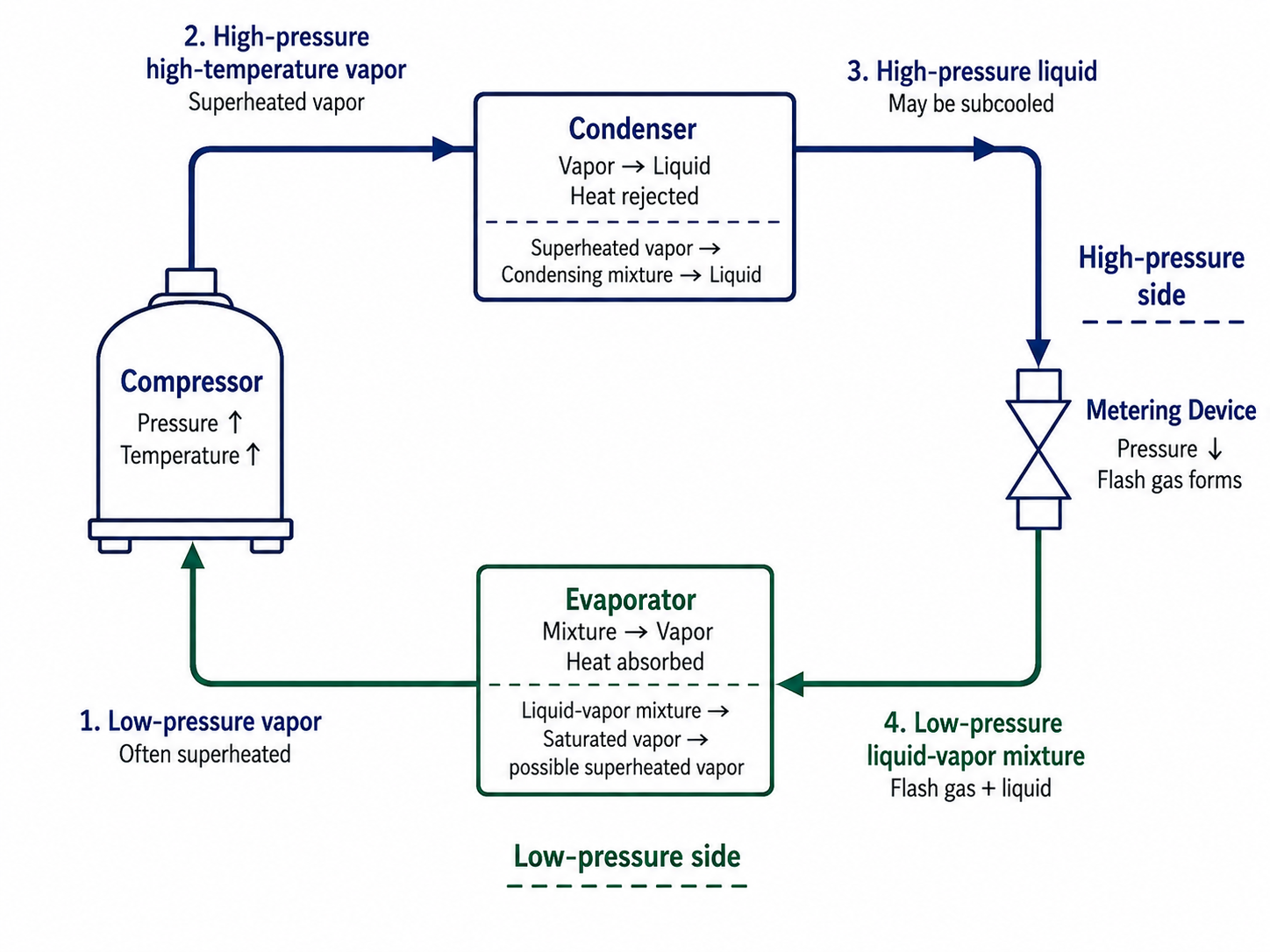
Figure 4.2.1 – Typical refrigerant states around the vapor-compression refrigeration cycle.
AI-generated instructional figure: It may contain visual inaccuracies. Use the accompanying lesson text and cited authoritative sources to verify technical and regulatory details.
EPA 608 Exam Focus
What Students Must Remember
The basic state sequence is:
Low-pressure vapor
→ Compressor
→ High-pressure high-temperature vapor
→ Condenser
→ High-pressure liquid
→ Metering device
→ Low-pressure liquid-vapor mixture
→ Evaporator
→ Low-pressure vapor
High-priority points:
- Compressor inlet
- Low pressure.
- Vapor.
- Often superheated.
- Compressor outlet
- High pressure.
- High temperature.
- Vapor.
- Condenser
- Rejects heat.
- Vapor changes toward liquid.
- Condenser outlet
- High-pressure liquid.
- May be subcooled.
- Metering device
- Creates the major pressure drop.
- Produces a low-pressure mixture.
- Some liquid flashes into vapor.
- Evaporator inlet
- Low-pressure liquid-vapor mixture.
- Evaporator
- Absorbs heat.
- Remaining liquid boils.
- Evaporator outlet
- Low-pressure vapor.
- Often superheated.
- Compressor raises pressure.
- Metering device lowers pressure.
- Condenser changes vapor toward liquid.
- Evaporator changes liquid toward vapor.
- Superheat means vapor temperature is above saturation temperature.
- Subcooling means liquid temperature is below saturation temperature.
State-Sequence Memory Table
| Exam Clue | Correct State / Location |
|---|---|
| Enters compressor | Low-pressure vapor |
| Leaves compressor | High-pressure high-temperature vapor |
| Enters condenser | High-pressure vapor |
| Leaves condenser | High-pressure liquid |
| Enters metering device | High-pressure liquid |
| Leaves metering device | Low-pressure liquid-vapor mixture |
| Enters evaporator | Low-pressure liquid-vapor mixture |
| Leaves evaporator | Low-pressure vapor |
| Pressure rises | Compressor |
| Pressure drops sharply | Metering device |
| Vapor changes toward liquid | Condenser |
| Liquid changes toward vapor | Evaporator |
Typical Exam Question Patterns
Students may be asked to:
- Identify the state entering the compressor.
- Identify the state leaving the compressor.
- Identify the state leaving the condenser.
- Identify the state leaving the metering device.
- Identify where the liquid-vapor mixture enters the cycle.
- Identify where vaporization occurs.
- Identify where condensation occurs.
- Determine which component raises refrigerant pressure.
- Determine which component produces flash gas.
- Distinguish high-pressure liquid from low-pressure mixture.
- Identify where superheated vapor can exist.
- Identify where subcooled liquid can exist.
Common Mistakes and Confusing Points
Mistake 1: Saying Liquid Normally Enters the Compressor
A conventional vapor-compression compressor is intended to receive vapor.
Correct simplified state:
Compressor inlet = low-pressure vapor
Mistake 2: Saying High-Pressure Liquid Leaves the Compressor
The compressor handles vapor.
Correct state:
Compressor outlet = high-pressure high-temperature vapor
Mistake 3: Saying the Condenser Raises Refrigerant Pressure
The compressor raises pressure.
The condenser rejects heat and changes vapor toward liquid.
Mistake 4: Saying the Refrigerant Leaves the Condenser as Low-Pressure Liquid
The condenser is on the high side.
Correct simplified state:
Condenser outlet = high-pressure liquid
Mistake 5: Saying the Metering Device Outlet Is All Liquid
The pressure drop causes part of the liquid to flash.
Correct simplified state:
Metering-device outlet
= low-pressure liquid-vapor mixture
Mistake 6: Confusing Flash Gas With Evaporator Vaporization
Flash gas forms during pressure reduction across the metering device.
Additional vaporization occurs in the evaporator because the refrigerant absorbs heat from the load.
Mistake 7: Saying the Evaporator Receives High-Pressure Refrigerant
The evaporator operates on the low-pressure side.
Mistake 8: Saying the Evaporator Rejects Heat
The evaporator absorbs heat.
The condenser rejects heat.
Mistake 9: Assuming Condenser Outlet Liquid Is Always Exactly Saturated
It may be subcooled.
The simplified state “high-pressure liquid” does not specify one universal degree of subcooling.
Mistake 10: Assuming Evaporator Outlet Vapor Is Always Exactly Saturated
It is often superheated before reaching the compressor.
The exact amount depends on the system and operating condition.
Concept-Check Questions
Question 1
What is the typical simplified refrigerant state entering the compressor in a vapor-compression refrigeration system?
A. High-pressure liquid
B. Low-pressure vapor
C. Low-pressure liquid only
D. High-pressure liquid-vapor mixture
Question 2
What is the typical refrigerant state immediately leaving the compressor?
A. Low-pressure saturated liquid
B. Low-pressure liquid-vapor mixture
C. High-pressure high-temperature vapor
D. High-pressure liquid
Question 3
What happens to the refrigerant as it passes through the condenser under normal cooling operation?
A. It absorbs heat and changes from liquid toward vapor.
B. Its pressure rises sharply because the condenser compresses it.
C. It remains entirely superheated vapor from inlet to outlet.
D. It rejects heat and changes from vapor toward liquid.
Question 4
What is the typical simplified state of refrigerant leaving the condenser?
A. High-pressure liquid
B. Low-pressure vapor
C. Low-pressure liquid-vapor mixture
D. High-pressure vapor only
Question 5
What typically leaves the metering device and enters the evaporator?
A. High-pressure superheated vapor
B. High-pressure liquid only
C. Low-pressure liquid-vapor mixture
D. Low-pressure vapor only
Question 6
Why does some refrigerant form flash gas as it passes through the metering device?
A. The compressor adds heat directly to the metering device.
B. The large pressure reduction causes part of the liquid refrigerant to vaporize.
C. The condenser raises the refrigerant above the critical point.
D. The evaporator forces all refrigerant to condense before entry.
Question 7
Which statement best describes refrigerant behavior through the evaporator?
A. A low-pressure liquid-vapor mixture absorbs heat and changes toward vapor.
B. High-pressure vapor rejects heat and changes toward liquid.
C. Low-pressure vapor is compressed into high-pressure vapor.
D. High-pressure liquid is subcooled by the compressor.
Question 8
Which statement about superheat and subcooling around the cycle is correct?
A. Superheat applies only to liquid and subcooling applies only to vapor.
B. Every system must have exactly the same amount of superheat and subcooling.
C. Subcooling means vapor is above saturation temperature.
D. Superheated vapor can occur near the evaporator outlet and compressor inlet, while subcooled liquid can occur near the condenser outlet and liquid line.
Answers and detailed explanations will be provided in
4.11 - Answers and Explanations.md.
Section Summary
The refrigerant changes pressure, temperature, and phase as it moves through the vapor-compression cycle.
The most important state sequence is:
Low-pressure vapor
→ Compressor
→ High-pressure high-temperature vapor
→ Condenser
→ High-pressure liquid
→ Metering device
→ Low-pressure liquid-vapor mixture
→ Evaporator
→ Low-pressure vapor
Remember:
- Compressor inlet → low-pressure vapor.
- Compressor outlet → high-pressure high-temperature vapor.
- Condenser → refrigerant rejects heat and changes toward liquid.
- Condenser outlet → high-pressure liquid.
- Metering device → pressure drops and flash gas forms.
- Metering-device outlet → low-pressure liquid-vapor mixture.
- Evaporator → refrigerant absorbs heat and changes toward vapor.
- Evaporator outlet → low-pressure vapor.
- Real systems can include superheated vapor and subcooled liquid.
- Do not assume one universal amount of superheat or subcooling.
The next section maps these refrigerant states to the high side, low side, suction line, discharge line, and liquid line.
See Section 4.3 - High Side Low Side and Refrigerant Lines.
References
Project Source
- Current EPA Section 608 teaching-material project outline, Module 4 — Refrigeration Cycle Components Gauges and Pressure-Temperature Relationships, Section 4.2. Required scope: low-pressure vapor entering the compressor, high-pressure high-temperature vapor leaving the compressor, condensation, high-pressure liquid leaving the condenser, pressure reduction through the metering device, liquid-vapor mixture entering the evaporator, vapor leaving the evaporator, and Figure 4.2.1.
EPA 608 Teaching Reference
- International Training Institute for the Sheet Metal and Air Conditioning Industry, EPA Section 608 Study Guide, refrigeration-cycle discussion. The cycle description identifies high-pressure liquid entering the metering device, pressure and saturation-temperature reduction, evaporator heat absorption and boiling, low-temperature low-pressure vapor leaving the evaporator, compression to high-temperature high-pressure vapor, condenser heat rejection and condensation, and high-pressure liquid leaving the condenser.
HVAC Technical References
-
Rex Miller and Mark R. Miller, HVAC Licensing Study Guide, 3rd ed., refrigeration servicing discussion. The text describes vapor traveling from the evaporator through the suction line to the compressor, compression raising vapor pressure and temperature, condenser heat rejection converting high-pressure vapor to high-pressure liquid, and liquid refrigerant flowing toward the evaporator through the metering restriction.
-
Justin Kauwale, Mechanical PE: HVAC & Refrigeration Textbook, 2025 ed., vapor-compression refrigeration cycle and pressure-enthalpy discussion. The text describes high-pressure liquid entering the expansion device, throttling to a low-pressure liquid-vapor mixture, flash-gas formation, evaporator vaporization, compression, condenser heat rejection, superheat, and subcooling.
-
Edward G. Pita, Air Conditioning Principles and Systems: An Energy Approach, 4th ed., refrigeration fundamentals, phase change, saturation, superheated vapor, subcooled liquid, and vapor-compression system concepts.
-
NCEES, PE Mechanical Reference Handbook, Version 2.0, refrigeration-property tables and pressure-enthalpy diagrams used as supplemental engineering references for refrigerant state interpretation.